



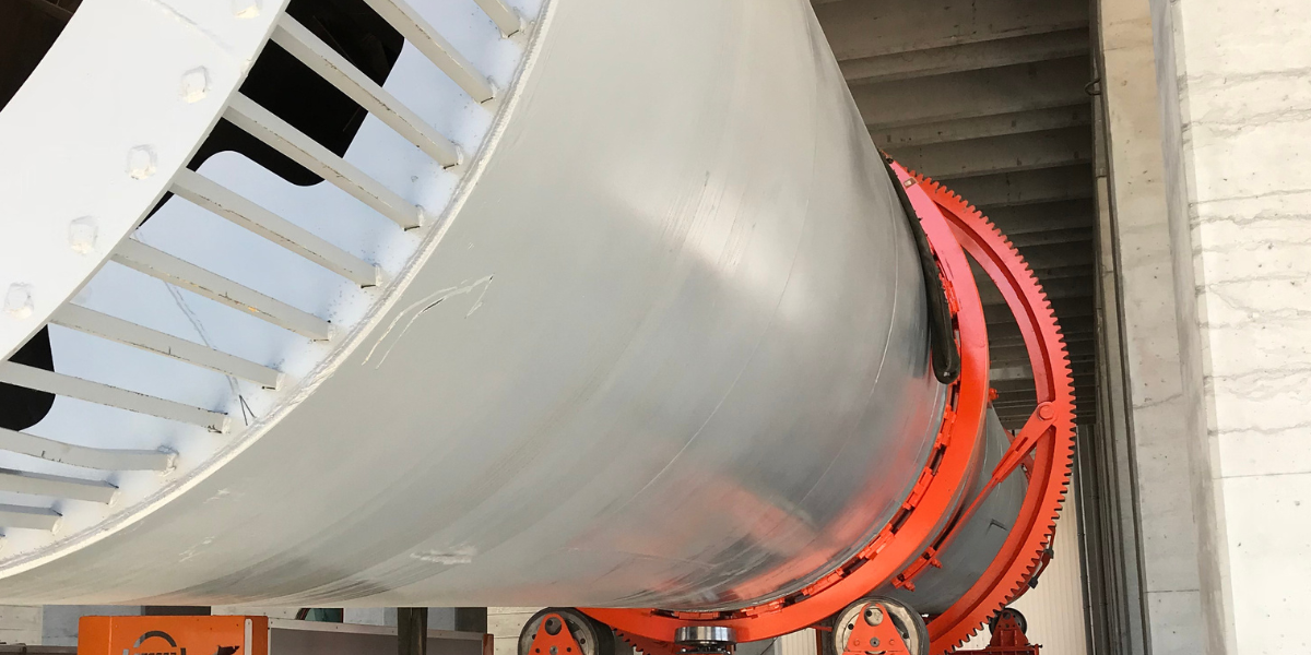
Of all the internal design parameters in a rotary drum dryer, flights and lifters are the ones that plant engineers are most likely to find underdocumented in their equipment files – and the ones they’re most likely to have to troubleshoot without much reference material. When a dryer is producing non-uniform outlet moisture, when dust generation from the drum is higher than expected, or when outlet moisture is consistently biased toward one side of the product specification band, the flight geometry is often where the root cause sits.
We’ll cover what flights and lifters actually do inside a rotating drum, the geometry variables that determine how they perform, how to match the design to the material and the process, and the most common failure modes that show up in practice.
What Flights Actually Do
In a direct rotary drum dryer, the drying of the material isn’t achieved primarily by contact between the material and the drum shell. It’s achieved by cascading the material through the hot gas stream – showering granules or particles from the flights in a curtain across the drum’s cross-section, where they are exposed to the flowing gas on all surfaces rather than just on the surface of a slowly rolling bed.
Flights are internal plates, usually welded to the drum shell, that pick up material from the bed at the bottom of the drum as the drum rotates, carry it up and around, and then release it to fall through the gas stream when the angle of the flight relative to the material’s repose angle allows the material to slide off. The curtain of falling particles – the shower pattern – is what provides the dominant mechanism for heat and mass transfer in a direct-fired rotary drum dryer.
Without flights, a rotating drum would still dry material by tumbling it in the bed at the bottom of the shell, but the exposed surface area per unit mass of material would be a tiny fraction of what’s achieved through showering, and the gas-to-material contact would be confined to the upper surface of the bed rather than distributed across the full drum cross-section. The improvement in heat transfer achieved by well-designed flights relative to a plain drum can be meaningful – the degree of improvement depends on the material, the flight design, and the drum geometry, and varies from one application to another.
Key Geometry Variables
Flight height is the radial projection of the flight from the drum shell toward the centreline. Taller flights can pick up more material per revolution, while flight shape, material properties, and drum speed determine how far particles fall through the gas stream before landing back in the bed. A longer fall increases the exposure time of individual particles to the gas, but it also increases the impact velocity when they land – which can be a problem for friable materials or for granules that are still relatively fragile at the drum’s feed end.
For NPK fertilizer granules, flight height and shape are sized so that material releases progressively across the drum’s cross-section. Unsuitable flights can carry material too high, causing excessive drop heights, or release it too early to provide a well-distributed shower across the full cross-section.
Flight angle controls when and how the material releases from the flight surface as the flight rotates past the horizontal. A flight with a 90° angle to the drum shell will hold material until the drum has rotated it to a position where gravity pulls the material off the flight face. A change in flight angle can advance or delay release, depending on the flight profile, material properties, and rotation speed. The release angle determines where in the drum’s cross-section the shower begins and therefore how the curtain is distributed.
Most dryer flights use a fixed angle, but two-stage flight designs – where the flight has an outer shelf and an inner shelf at different angles – are used in some applications to control the progressive release of material, or to extend the dwell time of the material in the shower zone.
The number of flights affects how many curtains of material are falling simultaneously across the drum cross-section. More flights can produce a denser, more uniform shower pattern, which distributes material more evenly and reduces the fraction of gas that passes through the drum without making meaningful contact with the product. Fewer flights, or flights that are worn down, produce a sparser shower with more gas bypass through the open zones.
The number of flights is typically expressed relative to the drum diameter, with circumferential spacing selected for the required flight loading, depending on the material characteristics and the required shower density. The right number for a given application is determined by the material’s bulk density, its particle size distribution, and the gas velocity inside the drum.
Matching Flight Design to Material
The flight geometry that works well for a coarse, free-flowing granule material – like a 3–4 mm NPK fertilizer granule – is different from what’s appropriate for a fine, dusty mineral product or a wet, sticky process intermediate.
For granular NPK product: the material can be relatively coarse and free-flowing after granulation, so the flights can be designed to carry a full load before releasing. The main constraints are avoiding excessive drop heights that would cause granule attrition, and ensuring the flight angle releases material before it’s carried past the top of the drum (which can increase drop height and attrition).
For fine powders or materials with a broad particle size distribution: the flight geometry needs to account for the tendency of fines to blow through the drum under the gas flow rather than participating in the shower. In these cases, reducing the gas velocity inside the drum (which may require increasing the drum diameter for the same airflow) is often more effective than adjusting flight geometry alone.
For wet or sticky materials at the drum’s feed end: material that is still close to its inlet moisture content may be sticky enough to adhere to the flight surface rather than releasing cleanly. Flights at the feed end of the drum in these applications are sometimes designed with a different angle or surface treatment to encourage material release, or the flight layout may use fewer, shorter flights in the feed zone where the material is wettest, transitioning to a fuller flight arrangement in the middle and discharge zones.
Common Flight Design Failures and How They Show Up
Worn or broken flights. Flight wear is a normal maintenance requirement in abrasive drying applications. As flights wear below their design height, the shower pattern becomes sparser and the heat transfer efficiency of the drum drops. The symptom is gradual: outlet moisture begins to trend upward at constant feed rate and burner conditions, or the burner has to fire higher than normal to maintain the outlet moisture target. If the wear is uneven along the drum length or around the circumference, the moisture content of the product becomes non-uniform. Regular inspection of flight condition during planned maintenance stops – and a defined replacement threshold based on minimum flight height – is the most reliable way to prevent wear from degrading process performance.
Incorrect flight design for the material. A flight design that was appropriate for one product grade may not be optimal for a different grade with different particle size, bulk density, or moisture characteristics. This tends to show up when a plant switches to a new product range and finds that the dryer performance is inconsistent even though the burner and airflow are unchanged. The shower pattern that worked for the original product may be too sparse or too aggressive for the new material.
Build-up on flight surfaces. In some NPK applications, particularly with hygroscopic raw material components or at higher than normal moisture levels, product can adhere to the flight surface rather than releasing cleanly. Progressive build-up changes the effective flight geometry – reducing the useful height and altering the release angle – and can eventually cause the flight to become a wedge that holds material against the drum wall rather than cascading it through the gas. Build-up is most common at the feed end of the drum where the material is wettest and the flights are most frequently loaded. Inspection access at the feed end is therefore one of the more practically important design features for dryers handling hygroscopic fertilizer materials.
Gas bypass. If the flight coverage around the drum circumference is insufficient, or if flights are missing or worn in a localised section, a proportion of the drying gas travels through the drum without making adequate contact with the product. This shows up as higher-than-expected exhaust gas temperature (because the gas hasn’t given up its heat to the product), higher outlet moisture for the same fuel input, and potentially elevated temperature in the product at the discharge end if the product that does contact the gas is being exposed to a higher thermal load per unit mass than the design intended.
Troubleshooting Non-Uniform Drying
When outlet moisture is non-uniform across the drum discharge cross-section – one side or one zone of the product stream consistently wetter than another – the root cause may be flight-related, but feed variation, airflow distribution, and particle segregation can also contribute. A uniformly operating drum produces a shower pattern that is well distributed across the cross-section, which delivers similar drying conditions to material regardless of which flight it was last carried by. Possible flight-related causes include: uneven wear on the flights around the circumference (producing a heavier shower from the unworn side), flight build-up on one section, or damage to specific flights that creates a dead zone in the shower pattern.
The diagnostic approach is to inspect the flights during the next planned stop with particular attention to circumferential uniformity – checking flight height, angle, and surface condition at multiple points around the drum rather than just at the most accessible access point.
Ceylan Machine & Process designs and manufactures rotary drum dryers with material-matched flight systems for NPK fertilizer, mineral, and chemical drying applications, with internal flight geometry tailored to product requirements. For technical enquiries on flight design or to discuss troubleshooting of an existing dryer system, contact our engineering team.