




Dust and fumes are usually the first operational complaint in a DAP plant, and they tend to appear long before anyone starts arguing about nameplate tonnage. The ammonia and fine particulate released from the granulation and drying stages have to go somewhere, either into a well-designed capture and treatment system, or into the plant environment and atmosphere. In a plant where the gas handling system was treated as an afterthought in the original design, or where the design was adequate for the intended operating conditions but wasn’t sized for variability, the consequences show up as regulatory non-compliance, housekeeping problems, product loss, and bearing failures from dust accumulation in rotating equipment.
We’ll cover the main emission sources in a DAP plant, the scrubber and dust capture options for each, the principles that govern ducting layout, and the compliance considerations relevant to plants in Africa and the Middle East.
Where Emissions Originate
The preneutralizer and reaction section. Hot ammonium phosphate slurry in the preneutralizer is in equilibrium with ammonia vapour in the gas space above it. Even when the neutralization ratio is being well controlled, some ammonia exists in vapour form over the slurry and must be vented and treated. The gas volume from the preneutralizer is relatively small compared to the dryer, but the ammonia concentration can be high, and the fluoride compounds present in WPA can also appear in the gas phase as hydrogen fluoride or silicon fluoride, requiring treatment before release.
The granulator is one of the larger ammonia emission sources in a well-run DAP plant. Hot slurry introduced into the granulator releases ammonia into the gas phase inside the drum as the slurry contacts the granule bed and as residual unreacted ammonia evaporates from the slurry surface. Additional ammonia is added intentionally in the ammoniator-granulator to complete the reaction. The gas leaving the granulator contains ammonia, water vapour, fluoride compounds, and fine product dust, a mixture that requires multi-stage treatment to bring to acceptable emission levels.
The dryer exhaust is the highest-volume gas stream in the plant. Hot air from the burner passes through the entire dryer volume, picking up fine granule particles and product-derived ammonia as it goes. The exhaust gas leaving the dryer can carry significant dust loadings, particularly during unstable periods when the granulator is producing a higher-than-normal fines fraction, and also contains the fluoride compounds and residual ammonia carried into the dryer with the granule feed.
The cooler exhaust carries less ammonia and less dust than the dryer exhaust, but the lower temperature of this gas stream introduces a condensation risk: if the gas contains acid aerosol or fluoride compounds, these can condense on the cooler exhaust ducting and scrubber surfaces as the gas cools below the dew point, requiring corrosion-resistant construction in that part of the gas path.
Dry product handling areas, the crusher, the screens, and the product conveying and storage sections produce dust from abrasion and transfer impacts. This dust is dry product material (MAP or DAP granule dust) and requires aspiration and collection at the source rather than wet scrubbing, since the dry product dust is recovered and recycled into the process.
Scrubber Design Options
The standard approach to treating the ammonia and fluoride-bearing gas streams from the granulator, dryer, and preneutralizer is a wet scrubbing system using an acid liquor as the absorbing medium. The scrubbing liquor is typically dilute phosphoric acid or the ammonium phosphate solution produced by the absorption reaction itself. As ammonia contacts the acid liquor in the scrubber, it reacts to form ammonium phosphate, which is recycled back to the preneutralizer or granulator as feed. This reactive absorption approach converts the ammonia emission into product and returns it to the process rather than disposing of it as waste.
Single-pass scrubbers pass the gas through a scrubbing vessel once and then release the treated gas. Multi-stage scrubber systems pass the gas through two or more scrubbing stages, each with fresh or recirculated liquor, achieving progressively lower ammonia concentrations in the exit gas. Whether a single-stage or multi-stage scrubber system is needed depends on the inlet ammonia concentration (which is higher when the plant is running with elevated recycle ratios or when the granulation is unstable) and on the emission limit applicable at the site.
Venturi scrubbers and packed tower scrubbers are both used in DAP plants. Venturi scrubbers are compact and have no internal packing that can foul or corrode, making them more suitable for heavily dust-laden gas streams where packing fouling would be a maintenance burden. Packed tower scrubbers achieve better gas-liquid contact for a given vessel volume and can achieve lower exit concentrations for clean or pre-treated gas, but require packing materials compatible with the scrubber liquor chemistry and access for periodic inspection and cleaning.
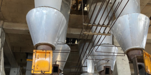
Cyclone pre-separation before wet scrubbing is standard practice for the dryer exhaust, which carries the highest dust loading of all the gas streams. Removing the coarser dust fraction in the cyclone before the gas enters the scrubber reduces the fouling rate on scrubber internals and reduces the loss of product into the scrubber liquor. The cyclone output, recovered dry product dust, can be recycled directly back to the granulator.
Ducting Layout Principles
The ducting layout between the emission sources and the treatment system has a significant effect on how reliably the gas handling system performs in practice. Several principles determine a well-designed layout:
Maintaining sufficient gas velocity in all ducts to prevent settled dust. In gas streams carrying fine product dust, there is a minimum transport velocity below which particles begin to settle on the duct floor. Duct sizing should ensure that the gas velocity stays above this minimum at all throughput conditions, including reduced-load operation. Dead zones, low-velocity sections, and horizontal runs without adequate flow velocity are the most common locations for dust build-up that eventually causes blockages and unplanned maintenance.
Avoiding sharp bends in dust-laden streams. Every change in gas direction in a dust-laden stream causes abrasive wear on the outer radius of the bend, and sharp bends cause more concentrated wear than gentle curves. Where bends are unavoidable, they should be designed with wear-resistant lining on the outer radius and access for inspection and replacement.
Minimising the distance between emission sources and the scrubber. Long duct runs in ammonia-bearing gas streams increase the potential for NH3 loss through duct wall permeation or leaks, and increase the heat loss from hot gas streams, which can cause condensation in the duct. Routing the gas treatment system as close as practical to the primary emission sources reduces these risks.
Providing access for cleaning and inspection. Duct sections that carry slurry aerosol or sticky dust will eventually accumulate build-up regardless of velocity control. Access panels at intervals along the duct, and at every bend and transition point, allow scheduled inspection and cleaning without major dismantling. In a plant designed without adequate duct access, routine cleaning becomes impractical, build-up accumulates over months, and the eventual cleaning event requires a longer production stop than a scheduled inspection would have.
Compliance Considerations for Africa and Middle East
Emission regulations for fertilizer plants vary significantly across the African continent and the Middle East, and the regulatory environment is an important input to the gas handling system design that cannot be ignored.
In some countries and regions, formal ambient air quality standards or point-source emission limits for ammonia and particulate matter exist and are actively enforced. Morocco and South Africa, for example, have established environmental frameworks with emission limit values that apply to industrial facilities including fertilizer plants. Operators and project developers in these jurisdictions need to obtain site-specific environmental impact assessments and emission permits, and the gas treatment system must be designed to meet the applicable limits with a reasonable compliance margin rather than at the limit itself.
In other jurisdictions across Sub-Saharan Africa and parts of the Middle East, formal emission regulations are either nascent, poorly enforced, or not yet extended to fertilizer manufacturing. In these environments, operators face a different but equally real pressure: international financiers, export market customers, and investors increasingly require that plants be designed and operated to recognised international standards, such as the IFC Environmental, Health, and Safety Guidelines for Fertilizer Manufacturing, regardless of local regulatory requirements. Plants built to international standards have better access to financing and to regulated export markets than plants built to the minimum local standard.
The practical implication for gas handling system design is to specify the scrubbing system for ammonia emission performance consistent with recognised international guidelines (IFC/World Bank EHS Guidelines typically specify NH3 emission levels below 30 mg/Nm³ as a reference value for ammonia), rather than designing to whatever the minimum local requirement is. This approach protects the plant against tightening regulations and maintains access to the widest possible range of financing and offtake partners.
Ceylan Machine & Process designs DAP and MAP fertilizer production facilities with integrated gas handling systems, including scrubbers, cyclone separators, and dust collection, designed to international emission standards. For technical enquiries on gas handling design for your facility, contact our engineering team.